Fast input-output control
Let’s make outputs 1 and 2 blink with 250 ms interval, and let’s make outputs 3 and 4 blink with 500 ms interval.
If you have Hardella IDE opened, you can either open
![]() code sample in the IDE, or you can create a new project with this code (
code sample in the IDE, or you can create a new project with this code (File > New > Project > Blinking leds).
As project opens you can see the following:
-
PRU Configuration – it describes which programs are assigned to each PRU core, it specifies PRU cycle length for each core, and it sets debounce intervals. In this particular case PRU Configuration is named
BlinkningLeds: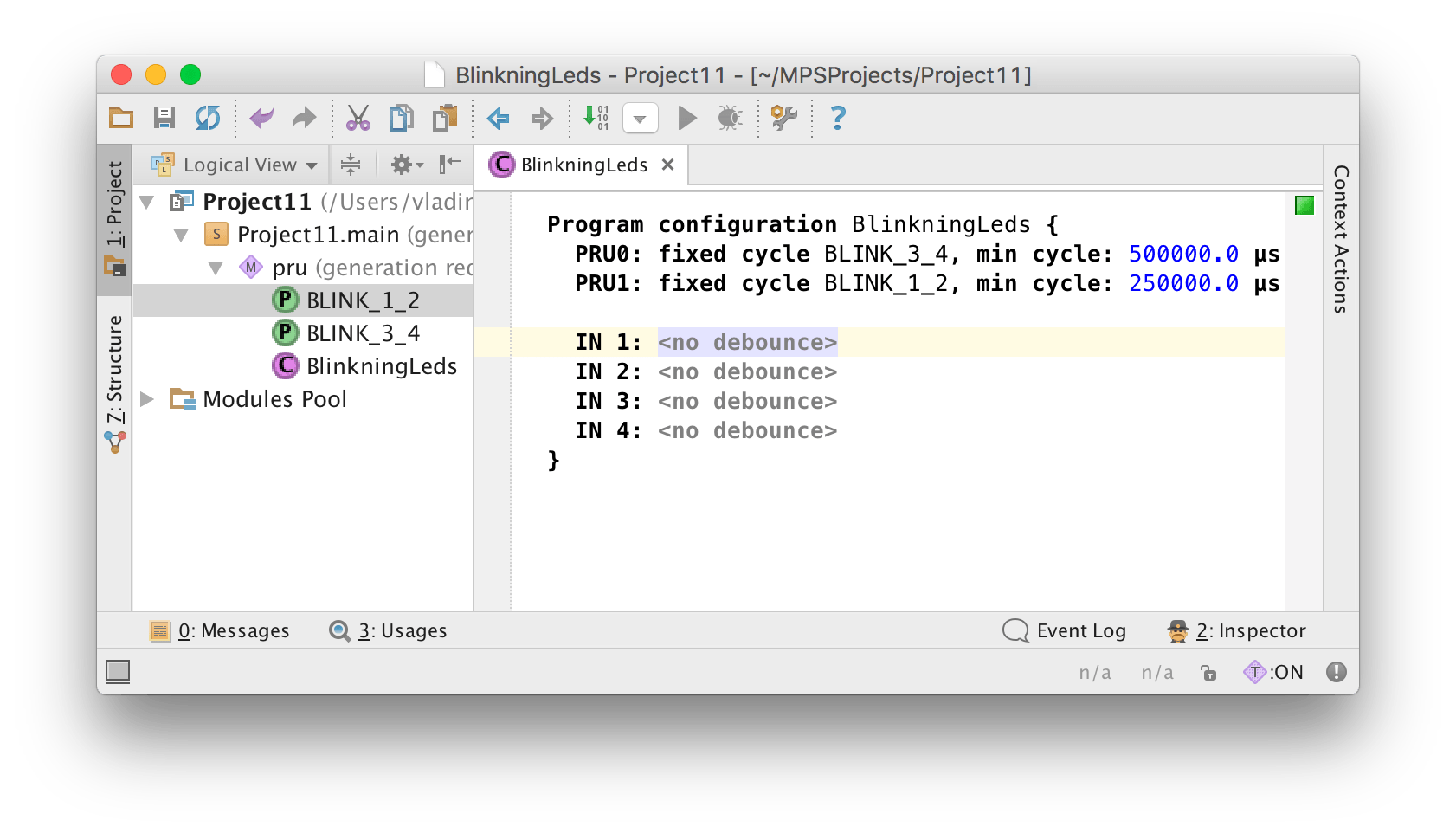
Debounce is disabled (see
no debounce). As you can see, PRU0 executesBLINK_3_4with 500 ms interval. That is PRU0 core will execute programBLINK_3_4at most once every 500 ms. -
Here’s the program for
PRU0. In this case it is namedBLINK_3_4:
It should not be that hard, however let’s discuss that in more details. The program writes the value of
stateintofast out 3(out3), then it assigns the value ofNOT statetofast out 4(seeout4). The value ofstatevariable is altered whenenableisTRUEonly.How can
enablechange its value? As you can see,enablevariable has CoDeSys data exchange configured (see data exchange). That meansenablewould be passed from the main PLC cycle, howeverBLINK_3_4would be executed at PRU cores. -
Here’s a program for
PRU1. It is namedBLINK_1_2: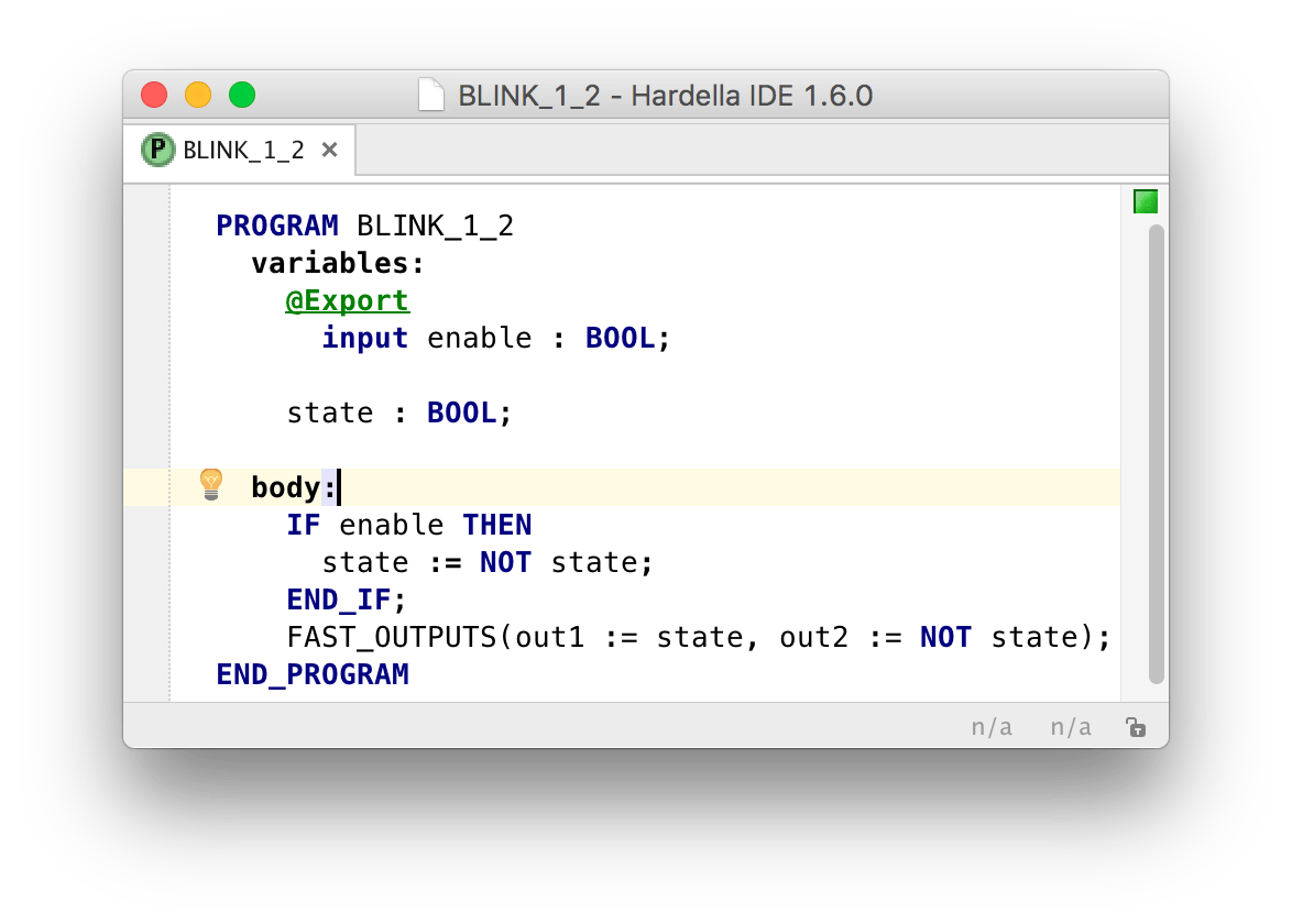
The contents is exactly the same as in
BLINK_3_4, exceptout1andout2are used.
As you build the project, Hardella generates MemoryTransfer CoDeSys programs that will have variables to control enable.
Here’s an example of the relevant program for PRU0:
PROGRAM BlinkningLeds_Pru0MemoryTransfer
VAR_INPUT
  BLINK_3_4_enable : BOOL;
END_VAR
...
That means in order to pass enable:=TRUE to PRU0 program, it is required to execute the following code in the main PLC program:
BlinkningLeds_Pru1MemoryTransfer(BLINK_3_4_enable := TRUE)
Leave a Comment